What is embedded software? Embedded software is sometimes known as firmware. Specifically, we design, code, and test software that is permanently or semi-permanently stored on the microprocessor or sometimes stored in some other nonvolatile memory location but is almost never stored on a hard drive or CD/ DVD. In colloquial terms, we say the software is “burned” onto the chip.
Embedded software is stored on many of our consumer products. Some examples are the following:
- Microwave ovens
- Washing machines
- Cell phones
- Automobiles (many microprocessors)
- Aircraft n Home theater systems
- Digital watches
- Nearly every Apple product
- Electric toothbrushes
- Electric razors
- Multimeters
- Calculators
- Many, many more
What do we need to know about the hardware?
Older embedded software was often “burned” onto microcontrollers or other integrated circuits (ICs) called one-time programmable chips. The only way to re-program these chips once they were used once was to use another part of the address range if sufficient space remained (usually not the case). The more sophisticated and expensive of these parts had a window on the top. When exposing the controller to UV, the EPROM would be erased. Tools exist to confirm that the devise has been erased.
More modern embedded software is often embedded on the microprocessor’s own flash memory, allowing for more flexibility in reprogramming the system. Some enterprises moved to the flashbased systems with the idea that field re-programmability would be possible. Re-programmability is only realistic when the customer has enough service infrastructure to support this level of sophisticated maintenance-if they don’t have this level of maturity, a flash-based system may be an expensive luxury.
Sometimes, the production test team may be able to recommend a microprocessor that has boundary scan capability. Boundary scan allows the microprocessor to “see” connections around itself and it can check these connections for pin states, voltages, or it can analyze design blocks inside an integrated circuit (with appropriate preparation and understanding). Boundary scan occurs quickly and without hardware test probes, often allowing the production test software to “see” portions of the circuit that may be invisible to the normal test method of using in-circuit testing (the “bed of nails” approach).
We will also want to understand the circuit designed by the electrical/ electronic engineers. The type of circuitry will dictate what we need to know about the some of the input and output pins on the microprocessor.
Embedded software will often communicate with other devices on the printed circuit board or on the network using a standard data bus.
Some of these data buses are as follows:
- Controller Area Network (CAN)
- Inter-integrated circuit (I2C)
- SAE J1587/J1708
- Serial Peripheral Interface (SPI)
- Universal serial bus (USB)
- Universal Asynchronous Receiver/Transmitter (UART)
- Firewire
The two most common languages in automotive design and development are
assembly language and C.
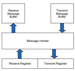
With embedded software, we must understand these data buses intimately, because we may sometimes have to use a pin that does not have these capabilities built-in to the microprocessor-this approach is often call “bit banging.” Bit banging involves a lot of work on the software side because all of the code for handling input and/or output must be written afresh-we have no support from the micro. Sometimes we have physical support from the microcontroller via dedicated pins. However, we will not have any message handling support with the exception of a single byte receive buffer.
What do we need to know about the software?
One of the challenges with embedded software lies with the microprocessor itself. Once we understand the printed circuit board design, we can then define a set of configuration values called “chip selects.” Chip selects will “tell” the micro whether the data is input or output. The chip select is a command pin on most integrated circuits which connects the input or output pins on the device to the internal circuitry of that device-the chip select logic can make the pin “deaf” or “mute.” In practical use, the chip select information will frequently be stored in the header file for a C program. By using “DEF” and “IFDEF” statement, the software engineer can make the header flexible enough to be used for repurposing the software.
The two most common languages in automotive design and development are assembly language and C. These two are used because it is relatively easy to conserve space on some of the smaller microprocessors. While memory space is less of a problem at the end of the first decade of the twenty-first century than it was in the 1990s, it is still a concern; not to mention, mature software engineers will nearly always write their code to be compact, improving performance in most cases.
What about software/hardware interactions?
Occasionally, we will see hardware and software interactions.
One source of problems is any kind of electronic noise:
- Electrostatic discharge
- Transient electronic or electrical pulses
- Inductive spiking from source of reactive power (any electric motor)
- Electromagnetic interference
- Open circuits
- Short circuits
- Over voltages
- Ambiguous voltages
- Over currents
Another source of hardware and software interaction is the occasional situation where the software gets “lost.” The designers may use an external watch dog circuit to reset the microprocessor if the watch dog circuit timer is not reset within a predetermined quantum of time. Many microprocessors have their own internal watch dog circuits; hence, one of the reasons they are often known as microcontrollers. In the 1990s these internal watch dog timers were less than ideal and some developers opted for both the internal as well as an external watch dog.
What is different about the design and development process?
In general, an embedded design and development process bears many similarities with the design and development of any other kind of software. A typical sequence of product launch reviews might look like the following:
- Receipt of customer specifications
- System requirements review
- System design review
- Software requirements review
- Preliminary software design review
- Critical software design review
- Verification and validation plan review
- Verification and validation
- Test readiness review
- Production readiness review
- Functional configuration audit
- Physical configuration audit
- Approval to release software to production
- Release to production test equipment
- Product launch
- Full production
Not every embedded process will look exactly like the preceding list, but they all will bear a family resemblance. Just as with any other software program, configuration management must be part of the product and process launch process from the very beginning of the programme.
Developer testing starts as soon as we have software and a target system for our In Circuit Emulator to connect. Some level of testing in earnest can occur as soon as we have software “burned” onto a microprocessor soldered to prototype printed circuit board. We will not be able perform any of the mechanical tests, but those tests are usually not particularly software dependent anyhow.
What do I need to know about embedded software testing?
To perform embedded software testing, we recommend four phases of testing.
These phases may take place concurrently and are as follows:
- Compliance testing
- Combinatorial testing
- Stochastic (or exploratory) testing
- Extreme testing
Compliance Testing
Compliance testing occurs when we test to requirements, whether these requirements are taken directly from a customer specification (when we have one) or derived internally from a requirements review. Compliance testing is the primary method we use to ensure that we are meeting all specifications. In the automotive industry, for example, we will verify that all gauges are meeting pointer sweep requirements in our instrument cluster (where we find the gauges on our dashboards).
Compliance testing has the defect of only testing for specification requirements and may provide an inadequate measure of the true performance of the system. Additionally, it can be difficult to record via specifications, all of the unwanted behaviors the product must not have. It is not very efficient, for example, to take time to identify all of the scenarios the product must not lock up. It could be sufficient to expect the product will not lock up. We expect our test engineers to be endeavoring to discern where the product fails rather than trying to prove that the product works!
Combinatorial Testing
We know that a very simple program can generate a vast number of potential test cases. With more complex programs (system), this number becomes astronomical. One technique we use to get around this problem originates with designed experiments. Many designed experiments are based on orthogonal arrays of test values. Two level testing for each input and output is often represented with a matrix of zeros and ones or pluses and minuses to indicate the two levels. More levels are possible, but increasing the levels increases the number of test cases exponentially. With digital inputs, two levels are adequate.
In essence, we will stimulate the inputs according to the recipe from any given row of our matrix and observe the behavior of the outputs. This situation means we must understand what the correct outputs are and be able to measure them.
One alternative to the orthogonal array is pairwise testing, perhaps best exemplified by James Bach’s wonderful Allpairs program. Allpairs takes input from a test file that is itself generated most commonly from a spreadsheet and creates a sequence of test cases that will exercise every pair. The amazing thing about Allpairs is that it holds up fairly well against commercial pairwise programs while remaining completely free! The pairwise approach has some defects, for example:
- It will only see two-way issues
- Interactions are generally invisible
- It is not complete
Even with the issues that pairwise testing exhibits, we still find it a reasonable member of the test engineer’s armamentarium-it should not be ignored.
Stochastic (Exploratory) Testing
Stochastic testing occurs when we allow a reasonably well-seasoned test engineer to go with their “gut” and feel their way about the product’s performance. During the development of numerous embedded automotive products, we have seen stochastic testing produce roughly the same amount of test failures as combinatorial testing. We are not recommending that stochastic testing supplant combinatorial testing but, rather, that they both have their place on our overall test strategy.
It is important that we have a means for recording what we do during stochastic testing. Spectacularly successful tests should be added to the existing suite of test cases and reused. We have seen some situations where program managers, customers, and software engineers have been aghast as the original suite of test cases metamorphoses into the ultimate horror show. They may say that the product will never see that level of stimuli. Then the test engineer walks them out to the field application of the product and makes the fault happen in a non-laboratory environment- demonstrating that it can and will indeed happen. However, we expect and hope the test suite grows as the test engineers learn more about the behavior of the product. Certainly the code is not static as we proceed through the development cycle and we should not expect the test program to remain static either.
Extreme Testing
Extreme testing occurs when we deliberately “torture” both the hardware and
software to see what happens under undesirable conditions.
Some examples of extreme testing include:
- Random voltages within the allowable voltage boundaries
- Voltage slews
- Deliberately introduced random noise on the data bus
- Extremely high bus loading (over 80% and sometimes over 90%) to see how the embedded software handles message dropping
- Cold and heat because variation in temperature can affect component performance, especially with LCD displays
- Rapid switching of hardware switches
- Slow voltage decay across the voltage boundary (which will sometimes cause a microprocessor “latch up,” wherein the micro ceases to function)
Extreme testing is another discipline where the test suite greatly benefits from the active imagination of the test engineer. Our list is only a subset of the possibilities.
Can I automate my testing?
We strongly recommend automated testing whenever this approach is feasible. The test team can use a language designed for this kind of testing; for example, National Instruments’ product Labview. The software should be able to read in the documented test cases, execute the test cases against the product, and finish by producing a meaningful and complete test report. It is also possible to execute the tests manually, and record the actions taken, thereby creating the source for the next run of the tests to be automated. As we might guess, it is nearly impossible to automate stochastic testing but is usually feasible to add the great ones to the automated test suite.
Automated test suites-indeed, all test suites-should be under complete configuration management.
That means we must also record the following about every piece of embedded software we test:
- Software version
- Specific parameter configurations
- Hardware version, including printed circuit board version
- Compiler name and type
- Compiler version n Suite version
What is the future of embedded software testing?
We suspect one of the next steps in embedded testing is to take a note from the hacker bad boys and literally attack the product. One way to accomplish this approach is to use “fuzzing,” wherein we modify inputs in an attempt to “get in” to the embedded software. We can make this method more powerful by giving it some intelligence in the form of a genetic algorithm (thanks to BJ Rollison of Microsoft Corporation).
It is also not out of the realms of possibility to use even more artificial intelligence-type of approaches to smash our product. We are talking about self-modifying code and other nasty probes.
Conclusion
We have provided a straightforward introduction to the science and art of embedded software development, especially the testing portions. While embedded software development bears a “genetic” resemblance to standard software development, it has its own peculiarities. These peculiarities provide a nice source of income for talented embedded software engineers and their demonic brethren, the test engineers.
About the Author
 Jon Quigley Jon M. Quigley PMP CTFL is a principal and founding member of Value Transformation, a product development training and cost improvement organization established in 2009, as well as being Electrical / Electronic Process Manager at Volvo Trucks North America. Jon has an Engineering Degree from the University of North Carolina at Charlotte, and two Master Degrees from City University of Seattle. Jon has nearly twenty five years of product development experience, ranging from embedded hardware and software through verification and project management.
Jon has won awards such as the Volvo-3P Technical Award in 2005 going on to win the 2006 Volvo Technology Award. Jon has secured seven US patents and a number of international patents. These patents range from human machine interfaces to telemetry systems and drivers aides. Jon is on the Western Carolina University Masters of Project Management Advisory Board as well as Forsyth Technical Community College Advisory Board. Jon also teaches Project Management classes at City University of Seattle via distance learning. Jon also is an expert at ITMPI (IT Metrics and Productivity Institute) giving webinars on numerous product development topics. He is also part of the Pm2Go experts.
Jon has membership in ASQ, SAE, AIAG and PMI (holding Project Management Professional Certification). Jon also has the CTFL certification from ISTQB.
Jon is the co-author or contributed to the books:
- “Project Management of Complex and Embedded Systems” ISBN – 978-1-4200-7205-1
- “Scrum Project Management” ISBN 978-1-4398-2515-0
- “Testing of Complex and Embedded Systems” ISBN 978-1-4398-2140-4
- “Total Quality Management for Project Managers” ISBN – 978-1439885055
- “Reducing Process Costs with Lean, Six Sigma, and Value Engineering Techniques”, ISBN – ISBN 978-1-4398-8725-7
- “Configuration Management: Theory, Practice, and Application” ISBN 978-148222935 May 1, 2015
- Contributor “Encyclopedia of Software Engineering” ISBN – 1-4200-5977-7 eISBN – 1-4200-5978-5
- Contributor to the e-book: “The Project Manager Who Smiled” by Peter Taylor. Catalog record for the book is available from the British Library ISBN 978–0–9576689–0–4 production June 2013
Jon is collaborating on another Project Management book (Q2 2015) through The Society of Automotive Engineers (SAE).
In addition to these books, Jon co-authored with Kim H. Pries two Professional Development Series focus books for Software Test Professionals (Redwood Collaborative Media):
- “Saving Software with Six Sigma”, ISBN 978-0-9831220-0-5
- “Aggressive Testing for Real Pros” ISBN 78-0-9831220-1-2
Additionally, he has co-authored scores of magazine articles that appear nearly twenty magazines.
He has also given numerous presentations at product development conferences on a variety of aspects of product development including testing and project management. Value Transformation has developed an introduction to product testing (software and embedded) at https://valuetransform.com/training/login/index.php it is free – register now
Email Jon at jon.quigley@valuetransform.com